MIT REFLECTORS
The thickness measuring devices MIT SCAN-T, MIT SCAN-T2 and MIT SCAN-T3 work with pulse induction, a further development of the eddy current method. For more information on the measurement method see menu item Measurement method under FAQ. The electromagnetic method requires the placing of metallic antipoles, so called reflectors, at the base of each layer that is to be measured. Please note that only the use of special reflectors that have been validated and optimized for the measurement system ensure the high accuracy and reliability of the method.


Reflectors in asphalt roads
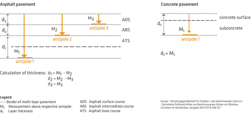
Asphalt roads consist of several pavement layers, each with a different thickness. As a control of layer construction, either each layer thickness is measured individually, i.e. layer after layer, or in total, as a whole.
To avoid compromising the bond of layers and in order to gain sufficiently strong signals, reflectors varying in size are integrated. In principle applies: the higher the layer to be measured - and thus the measurement range - the larger the reflector must be.
Reflectors in concrete roads
Concrete roads are built en bloc. In general, a distinction is made between bottom-layer and top-layer concrete. The only point to be observed is not to use aluminum reflectors in concrete. This is because during curing the concrete chemically reacts with the aluminum so that cavities may form in the road.
Functional diagram of layer thickness measurement
For inspection purposes, the reflectors have to be installed undisplaceably as indicated in the laying plan. The laying plan specifies the type, number and position of the reflectors in the road. For self-monitoring purposes, the reflectors may be placed directly in front of the paver.
Laying plan
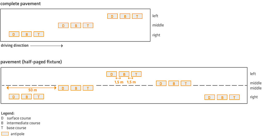
One measuring site comprises all the reflectors necessary for analyzing each paved layer at one location on the roadway. The respective reflectors are installed beneath each layer that is to be assessed. When the measurement reflectors are installed, care must be taken to exclude any influence on the measurement signals from foreign metals. Accordingly, it is imperative to keep a minimum distance of 1m between reflectors and of 1.5 m between reflectors and built-in road fitments, e.g. rain water drains or other dowel and tie bars. The measuring site is usually marked as such on the side of the road.
Each individual layer thickness is measured as specified under ZTV Asphalt-StB 07 at regularly distributed measuring sites across the construction area. 20 m is the distance required between measuring sites in short construction stretches (length about 500 m) is and 50 m in long construction stretches. However, it is necessary to collect data from at least 20 measurement sections. For roads up to 5 m in width, the measuring sites are arranged alternately to the right and left (in zigzag order). In multi-lane roads, three measuring sites are laid out in one line perpendicular to the edge of the road on the right, middle and left of each lane. This provides a sufficiently high statistical certainty for evaluating construction performance. If required, the contracting authority and the construction company may agree upon arrangements that deviate from regulations in specific situations.
The measuring device together with the reflectors specified for the measuring site form a technical unit. The reflectors available on the market differ in material and format. These fully cover the entire measuring range and all general applications in the field. The reflectors used are either of aluminum or galvanized steel. The usual formats found are sheet metals (circular and square or rectangular reflectors) and foils (square or rectangular reflectors). Only robust, market-conform and ready-made reflectors that have been certified for use with the measuring device are permitted for use at construction sites. The German TP D-StB 12 or STLK contain a list of approved materials and formats.
The following standard reflectors as per the TP D-StB 12 or STLK are available:
| Designation | Maximum measurement depth | Material | ||
|---|---|---|---|---|
| AL RO 07 | 12 cm | Circular plate ∅ 7 to 30 cm; Material: Al; 1.0 mm | ||
| AL RO 12 | 18 cm | Circular plate ∅ 7 to 30 cm; Material: Al; 1.0 mm | ||
| AL RO 30 | 35 cm | Circular plate ∅ 7 to 30 cm; Material: Al; 0.5 mm | ||
| ST RO 30 | 35 cm | Circular plate ∅ 30 cm; Material: Steel, 0.65 mm | ||
| AL 30 x 70 | 50 cm | Rectangle 30 x 70 cm; Material: Al; 0.1 / 0.15 / 0.3 mm | ||
| AL 30 x 100 | 50 cm | Rectangle 30 x 100 cm; Material: Al; 0.1 /0.15 / 0.3 mm | ||
| AL 16,5 x 16.5 | 30 cm | Square 16.5 x 16.5 cm; Material: Al; 0.1 and 0.15 mm | ||
| AL 33 x 33 | 40 cm | Square 33 x 33 cm; Material: Al; 0.1 and 0.15 mm |
Sustained quality of the measurement reflector ensures high accuracy and reliability of the electromagnetic measurement method. MIT Mess- und Prüftechnik GmbH validates all the reflectors it supplies batch-wise on its test stand. The test number can be found on the delivery note or invoice, or is attached to the product.
Additionally, MIT's circular plates that have been adapted based on the measurement systems MIT-SCAN-T2 or MIT-SCAN-T3 carry a stamp showing the MIT logo.
Circular sheet steel plates:
Circular plates are round plates of rolled sheet metal. They are robust against incidental damage during installation and as a result guarantee high precision measurements. The compactly designed circular plates can be laid down in front of the paver simply and with no waste of time. The direction of the measurement path over the reflector can be chosen randomly. This also allows performing measurements under unfavorable conditions (e.g. directly next to curbstones or on narrow lanes).
Circular aluminum plates
Circular aluminum plates are exclusively used for asphalt installation and on milled surfaces or unbound layers. They are available in various formats and are firmly fixed using MIT plate adhesive.
The measurement range is between 4 cm (from base of the asphalt intermediate layer), 12 cm (from base of the asphalt binder layer) and maximally 35 cm (from base of the asphalt base layer).
Aluminum is not temperature sensitive. It is therefore possible to perform thickness measurements by placing circular aluminum plates directly behind the paver or the compactor even on hot asphalt.
Circular steel plates
Since circular steel plates are not subject to corrosion through concrete, they are specially suited for thickness measurements in concrete. Because the total thickness of a concrete road pavement is usually of sole interest, it is generally sufficient to use steel plates 30 cm in diameter in this application situation. Further formats are currently not required. Circular steel plates may in contrast to circular aluminum plates be fixed using a stainless steel nail (see TP D-StB 12, section 2.2.6). Circular steel plates have to be laid at a distance of 2.5 m from larger metallic objects (e.g. baskets).
Aluminum foils
Foils made of aluminum are available in various ready-made rectangular and square formats. Approved formats and their measurement ranges are shown in the above table. The most frequently used foil sizes are 30 x 70 cm and 30 x 100 cm. Foils are generally used for measurements of layers > 40 cm. Rectangular foil formats should be inserted parallel to the direction of traffic and passed over perpendicular to their long sides. Square foils must always be passed over their center parallel to one edge - Attention: never pass diagonally! Only thick foils must be used (thickness at least 100 µm). Ready-made foil formats are preferable to those cut from a roll, because inaccurate trimming may produce incorrect formats and lead to inaccurate readings.
All reflectors as shown below are available through MIT-> directly to online shop
| Designation | Use | Layer type | Minimum cover | Measurement range | ||||
|---|---|---|---|---|---|---|---|---|
| AL RO 07 | Asphalt | Surface course | 1.5 cm | 1.5 - 12 cm | ||||
| AL RO 12 | Asphalt | Intermediate Course | 4 cm | 1.5 - 18 cm | ||||
| AL RO 30 | Asphalt | Base course | 12 cm | 4 - 35 cm | ||||
| AL QU 16.5x16.5 | Asphalt | Base course | * | up to 30 cm | ||||
| AL QU 33x33 | Asphalt | Base course | * | up to 40 cm | ||||
| AL RE 30x70 | Asphalt | Base course | * | up to 50 cm | ||||
| AL RE 30x100 | Asphalt | Base course | * | up to 50 cm | ||||
| ST RO 30 | Concrete | Lower Concrete | 12 cm | 4 - 35 cm |
Legend: AL (aluminum), ST (steel), CP (circular plate), SQ (square sheet metal/foil), RE (rectangular sheet metal/foil)
*) No limitation known. Minimum cover describes the mandatory material thickness required between reflector and the paved surface on a completed road construction.All common reflector sizes are available in our Shop. There you may find also Information About dimensions, packaging units, weight and prices as well as our terms of delive
MIT plate adhesive
MIT's plate adhesive is for fixing measurement reflectors for inspection tests. It is a bitumen-based, rapid and easy to process two-component adhesive. It is applied onto the plate before being installed where it hardens within 30 minutes.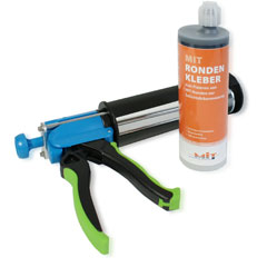
Advantage:
- Simple handling, cold processing
- Ready-mixed press cartridge
- No influence on layer thickness
Characteristics:
- Processing temperature: > 10 °C
- Surface temperature: > 5 °C
- Ambient temperature: 8 °C to 30 °C
- Solvent-free