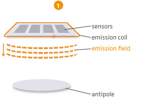
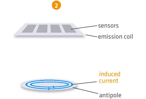
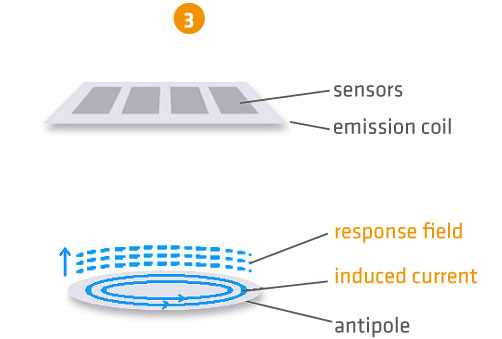
1. How does thickness measurement using pulse induction work?
2. Are reflectors required for measuring layer thickness with pulse induction?
3. Can the MIT-SCAN-T2 be used to measure layer thickness in existing roads that have no reflectors installed?
4. Do the measurement reflectors need to be stuck fast with glue?
5. Can circular plates also be fixed to the base with a nail?
6. What is the MIT wheeled spacer for?
7. Does steel toecap footwear influence measurements?
8. How often does the thickness device need to be calibrated?
9. Can measurement reflectors be self-made or self-cut?
10. Is the upper or bottom side of the measurement reflector relevant for measuring layer thickness?
11. Which components in the thickness measuring device are subject to wear and should be checked regularly?
1. How does thickness measurement using pulse induction work?
2. Are reflectors required for measuring layer thickness with pulse induction?
Yes. An antipole is always required for layer thickness measurement with pulse induction. (See FAQ on measuring principle).
3. Can the MIT-SCAN-T2 be used to measure layer thickness in existing roads that have no reflectors installed?
No. Unfortunately, this is not possible. The pre-placement of reflectors (antipoles) is a requisite of electromagnetic layer thickness measurement.
4. Do the measurement reflectors need to be stuck fast with glue?
For layer thickness measurement according to the TP D StB 12 test specifications, it is necessary to install reflectors “in an undamaged state, fully planar and fixed undisplaceably”. If sheet metals are used as reflectors, the easy-to-use MIT plate adhesive, applied sparingly, can be used for fixing them. Further information on MIT plate adhesive can be found here: MIT plate adhesive
5. May circular plates also be fixed to the base with a nail?
As specified in the TP D StB 12, aluminum circular plates should not be fixed to the base with a nail. Circular steel plates, on the other hand, can be fixed in their middle to the road base with a stainless steel nail (length: max. 5cm, diameter: max. 3mm).
6. What is the MIT wheeled spacer for?
The TP D StB 12 (Point 2.2.6 Measurement) requires the thickness device’s functionality to be measured before starting the day’s first measurement. For this, first the layer thickness of an existing measuring site is determined by a simple measurement run. This measurement must then be repeated using a metal-free spacer that has a thickness of 3.5cm (± 1 mm). The device is ready for use, if the difference between both measurements equals the thickness of the spacer. The MIT wheeled spacer is a mobile, compactly built spacer.
7. Does steel toecap footwear affect measurements?
Yes. All metallic objects such as steel toecaps in shoes, crash barriers and construction machines have an influence on the measurement result. Care must therefore be taken, that no metallic objects are present around the measuring probe within a radius of about 2 meters.
8. How often does the thickness device need to be calibrated?

In line with TP D-StB 12, thickness measuring devices must be calibrated at yearly intervals by a BASt-authorized institution (calibration laboratory) and have a valid calibration certificate. According to TP D-StB 12 only the use of thickness measuring devices with a valid calibration certificate is permitted. The valid calibration certificate (available in the carrying case) and the calibration mark (attached on the measuring probe) are to be kept available at the construction site.
9. Can measurement reflectors be self-made or self-cut?

The reflectors listed as approved in TP D StB 12 test specifications and the STLK (Catalogue of Standard Specification Texts), include aluminum foils as well as square, rectangular and circular sheet metals. They have been used for measurement of layer thickness for years and are reliable antipoles. Calibration data of the standardized reflectors are stored in the thickness measuring device, so users can achieve high measurement accuracy. The measuring system and the listed, officially approved reflectors form one technical electromagnetic thickness measurement entity.
In line with its quality assurance policy, MIT Mess- und Prüftechnik GmbH (MIT) validates the reflectors to ensure the required reliability and accuracy of the method.
Imitation or self-manufacturing of the measurement reflectors is not permitted. MIT shall assume no liability for any economic damages resulting from the use of imitated reflectors. Only with MIT's validated and method-harmonized measurement reflectors can accurate and reliable results be achieved. MIT equips the reflectors it has validated with a signet.
MIT also strongly advises against cutting aluminum foil from a roll. Trimming as a rule results in inaccurate reflector formats and thus deviating measurement outcomes. You should therefore only use pre-cut and manufacturer-validated foils.
10. Is the upper or bottom surface of the measurement reflector relevant for determining layer thickness?
The measuring device calculates layer thickness based on the lower surface of the installed reflector, i.e. its contact surface with the base.
11. Which of the thickness measuring device's components are subject to wear and should be checked regularly?
The thickness measuring device is robust and designed for use in various environments (such as on hot mix asphalt or when it rains).
The following parts however require a check-up from time to time:
- battery (its lifetime is generally four years)
- wheels (these need to be cleaned regularly, since deposits can affect measurement outcomes).
MIT offers practitioners a spare parts service tailored to their needs. We will gladly provide advice concerning the replacement of components and any required repairs in case of problems.
1. Can the MIT-SCAN2-BT be used to measure all types of dowel bars?
2. Is it possible to measure dowel types for which the device has not been calibrated?
3. Is it also possible to measure dowel bars that are installed using baskets?
4. Can the positions of dowels be determined before the joint is cut?
5. How long will it take to assess several joints?
6. Do users need the software MagnoProof?
7. The joint to be measured is longer than the rail system. Is it still possible to measure the joint?
8. Which of the measuring device's parts are subject to wear and should be checked regularly?
9. Does steel toecap footwear affect measurements?
10. May users replace the battery?
11. Does the dowel position measuring device have to be calibrated annually?
1. Can the MIT-SCAN2-BT be used to measure all types of dowel bars?
This is possible, in principle. The device has to be calibrated for use with the type of dowels that are to be measured. MIT offers and can perform calibrations with all conventional dowel sizes.
2. Is it possible to measure dowel types for which the device has not been calibrated?
If the device has not been calibrated for use with the installed dowels, the dowel positions cannot be calculated. A measurement can nonetheless be taken. The device visualizes the measured data (color chart) and general estimates of dowel positions can be made.
3. Is it also possible to measure dowel bars that are installed using baskets?
Currently, automatic calculation of dowel positions installed in baskets is not possible. In this case, as with not calibrated dowel bar types, visualization of the measured data (color chart) provides information on dowel positions. The user interprets the measurement signals.
4. Can the positions of dowels be determined before the joint is cut?
Yes. As soon as the concrete is walkable, a measurement using the MIT SCAN2 BT system is possible. This measurement delivers important information that enables the user to control the joint line and, if required, correct the position of where the joint is to be cut.
5. How long will it take to assess several joints?
Setting up the measurement system takes about ten minutes. The assembled rail system can be transferred as it is from joint to joint during the day of measurement taking. The actual time it takes to measure a joint is less than one minute. Transporting the rail system to the next joint and aligning it along the joint is simple and fast.
6. Do users need the software MagnoProof?
The MagnoProof software evaluates all acquired measurement data and generates reports and graphs of the positions of all dowels of one measurement section. It is included with the delivery of the measurement system.
7. The joint to be measured is longer than the rail system. Is it still possible to measure the joint?
There are two ways the joint can be measured in this case:
Measure the joint in two consecutive measurements. After the first measurement has been taken, shift the rails and then take a measurement of the second section.
The rail system can also be extended variably, so that longer joints can be measured in one run. These lengthening elements can be ordered separately.
8. Which of the thickness measuring device's components are subject to wear and should be checked regularly?
Basically, the device's design is very robust. Yet, various of its parts are subject to wear:
- The white sliders on the wheel-guided probe wear down after some time. This means the probe cannot be guided precisely over the rails. The sliders are available as spare parts and can be exchanged by the user.
- Wheels showing wear may lead to false path measurement.
- The battery integrated in the device should be exchanged within five years at the latest.
- The measurement electronics are wear-free. However, it is recommended to have the manufacturer check the device every two years. This will ensure the system's measurement accuracy.
For users of our dowel position measuring system, we offer our demand-oriented repair and spare parts services. We will be happy to provide replacement advice and support, if required.
9. Does steel toecap footwear affect measurements?
Even small metallic objects, such as steel toecaps in footwear can affect a measurement if they are present within a radius of less than one meter around the measuring device. While pulling the measurement device, the user must take care to keep a distance of at least one meter from the rail-guided probe. This is generally the case.
10. May users replace the battery?
Yes. For this, only the housing cover needs to be removed.
11. Does the dowel position measuring device have to be calibrated annually?
Annual calibration is currently neither mandatory, nor necessary. However, it is recommended to have the manufacturer check the device every two years. It includes a check of the electronics and hardware of the MIT-SCAN2-BT. This can ensure unrestricted functionality and accuracy of the measuring device.